30 January 2013

Iterative Closest Points (ICP)

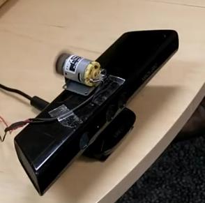
From the depth images captured by IR camera, we can derive point clouds which show the 3D shape of the target. An example of point clouds is shown in figure 1. An registration issue arises when we have 2 point clouds of same scene captured by different camera from different point of view. The overall goal is to find a transformation which can bring one point clouds as close to another clouds as possible. The most common method is called Iterative Closest Points (ICP) and various variants of it have been well developed.

Figure 1 Point clouds produced from Kinect depth data
We will call the first set of points model points, and the other set data points. The model point set are denoted Q = {q1, q2, q3,...,qn} and data point set P = {p1, p2, p3,...,pn}. We can set an objective function (error metric) E to evaluate the distance between two set of points. A popular metric is sum of squared errors:
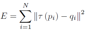
which is squared distance from points in one cloud to their nearest neighbours in the other after the transformation τ.
There are various kind of transformation we can apply including rigid or non-rigid depends on the task. Here we use only rotation (R) and translation (T) only since the scene (patient) doesn't deform much and it keeps the calculation realistic and simple. Therefore, the objective function can be rewritten as:
Please keep in mind that the correspondence of model and data points are unknown. To this end, the ICP try to approximate the correspondence based on the nearest neighbour before transformation τ. The ICP performs following steps iteratively:
  1. Matching: for every data point the nearest neighbour in the model point set is found.
  2. Minimization: the objective function is minimised and the transformation parameters are estimated.
  3. Transform the data points using the estimated transformation.
  4. Iterate (re-matching the new data point with model point).
The algorithm is terminated based on the predefined number of iterations or relative change of objective function.

Reference:
Hans, Kjer and Jakob Wilm, 2010. Evaluation of surface registration algorithms for PET motion correction. Bachelor theis, Technical University of Denmark.

28 January 2013

Working space of Kinects in ambulance

Since the 3D scan of patient body happens in ambulance, a study of how to position Kinect to achieve best filed of view of body is necessary. The Kinect should be placed neither too far away from nor too close to patient due to the operational range of the Kinect mentioned in the last post. The basic geometry and triangulation will be used to derive the interval equation of the configuration in which the best field of view can be guaranteed and the overlays between two Kinects are optimized. As the exact model of ambulance is undefined yet, the calculation will use symbols to represent parameters of the configuration.
Figure 1 Schematic diagram of the ambulance

As shown in the figure 1, the ambulance has internal size of W by H (only transverse plane is shown). The patient will lie on the bed which is height of h(bed). Here we assume that the bed is placed at the centre of ambulance. The Kinect camera is placed on the wall with height of (h(bed)+Δh). The middle line of Kinect should point to the middle of the bed to get more completed view of the patient.
Based on simple triangulation, the best angle between the central view line and the wall is:


then the lower bound of the field of view is:

and the upper bound would be:


In order to satisfy the operational range (near field mode), both lower and upper bound should have:
Given the internal width of the ambulance and the relative vertical distance between Kinect and the bed, the best angle to place the Kinect can be calculated. The bounds of the filed of view are then checked to ensure the patient is in the best operational range.
For the other Kinect on the another side, it can be placed at the same pose since they are symmetrical in this case.

27 January 2013

Hardware design of Kinect

The key components of Kinect are indicated in the figure 1, they are:
  1. Multi-array microphone: This is an array of four microphones that can isolate the voices of the user from the noise in the room. By comparing the delay in each microphone, the voice source can be located.
  2. IR laser emitter: Actively emitting near infrared spectrum, which can be distorted by uneven surface and then randomly formed as reflected speckles. The speckles can be received by infrared camera (No. 3 in the figure).
  3. IR camera: Capturing infrared signal which can be converted into depth map.
  4. Motorized tilt: The motor can be programmed in order to achieve the best view angle.
  5. USB cable: Transmitting video stream, depth stream and audio stream. The extra power source must be connected to get all functions of Kinect. (The power of Kinect is 12W while the power of normal USB cable is 2.5W)
  6. RGB camera: Capturing colour video stream.

Figure 1 Structure of Kinect and its key components
The "heart" of Kinect is the PS1080 system on chip (SoC) produced by PrimeSense. It is a multi-sensor system which can provide depth image, colour image and audio signal at the same time. As shown in figure 2, PS1080 encode the IR light and project it to the scene while IR camera capture the IR light and send the signal back to PS1080. The PS1080 process the signal and retrieve the depth image and combine it with the corresponding colour image. Since the audio part is not important  in this project so far, no detail of it will be introduced.

Figure 2 Recommended design of Primesense chip
The field of view in the system is 57 degrees horizontal, 43 degrees vertical, and the operational range is between 0.8 meters and 4 meters (normal mode). For the near mode, Kinect can detect object as close as 0.4 meters and as far as 3 meters (as shown in figure 3).
Figure 3 Types of values returned by the runtime
Specification of Kinect (referenced from here)

Kinect
Array Specifications
Viewing angle
43° vertical by 57° horizontal field of view
Vertical tilt range
±27°
Frame rate 
(depth and color stream)
30 frames per second (FPS)
Audio format
16-kHz, 24-bit mono pulse code modulation (PCM)
Audio input characteristics
A four-microphone array with 24-bit analog-to-digital converter (ADC) and Kinect-resident signal processing including acoustic echo cancellation and noise suppression
Accelerometer characteristics
A 2G/4G/8G accelerometer configured for the 2G range, with a 1° accuracy upper limit.


26 January 2013

Interference problem of multiple Kinects (1)

Why interference?
"Multiple Kinects tend to interfere with one another. A Kinect measures the depth of a point by projecting a pattern of infrared dots into the scene and detecting how far they appear shifted due to parallax. This is great when there is only one Kinect but if you have more than one there is no way of separating out their dots. What this means is that one Kinect could project an infrared dot that another Kinect "sees" as its own and hence incorrectly estimates the distance."
Solutions: 
  • Time division multiplexing approach
Schroder et al. [1] implemented a time decision multiplexing approach, where IR emitter on each Kinect is blocked in turn so that the IR pattern don't interfere. However, the frame rate of depth images are reduces with the number of Kinects.
  • Shake n Sense (moving Kinect)
By adding a motor with an offset-weight vibration to one of the Kinects, the IR signals from IR camera are "modulated. The IR camera of the Kinect will move in harmony, which means that depth sensing works as normal, though a little blurs are introduced. Butler et al. [2] proved that even minor almost imperceptible motion of the sensor in this way causes blurring of structured light patterns from other units which serves to eliminate most of the cross-talk.

  • Hole filling algorithm
Instead of preventing the interference, Maimone and Fuchs [3] used a hole filling algorithm to fill missing depth caused by the interference and median filtering to reduce the noise. Their system can present real-time merging of the data from multiple Kinect and keep frame rate at 30 fps.


Reference:
  1. Schroder, Y. and Scholz, A. and Berger, K. and Ruhl, K. and Guthe, S. and Magnor, M. Multiple kinect studies, Computer Graphics 2011.
  2. Butler, D.A. and Izadi, S. and Hilliges, O. and Molyneaux, D. and Hodges, S. and Kim, D., Shake'n'sense: reducing interference for overlapping structured light depth cameras, Proceedings of the 2012 ACM annual conference on Human Factors in Computing Systems.
  3. Maimone, A. and Fuchs, H. Encumbrance-free telepresence system with real-time 3d capture and display using commodity depth cameras, Mixed and Augmented Reality (ISMAR), 2011 10th IEEE International Symposium


Kinect Hacking:
http://idav.ucdavis.edu/~okreylos/ResDev/Kinect/

http://social.msdn.microsoft.com/Forums/en-US/kinectsdknuiapi/thread/a9635450-5ab6-4166-8391-75921e7f7ccf

https://groups.google.com/forum/?fromgroups=#!topic/openni-dev/IDVsj42ezKg

24 January 2013

First Meeting with George

First Meeting with George

Impression of the project:
1. Using one/two Kinect sensor(s) to reconstruct human 3D body in real-time.
2. After the initial reconstruction is finished, landmark recognition based on FAST exam should be applied.
3. User interface with sonographer who can indicate extra points of ultrasound scan.

Topics talked about:

  • One or two Kinect?

Lin came up with an idea called Kinect Fusion which used SLAM to track the positon of the camera. It may be over-complicated for starting the project.
By considering the complexity of the project, one Kinect should be a good starting point.
Considerations for choosing number of Kinects:
- Interference b/w two Kinects signal
- Shadowing from single point of view
- Field of view
- Registration b/t two frames from corresponding Kinect

  • FAST only require upper part of body, ignore lower part of body?
Depends on landmarks recognition method (capable for upper part of body).
  • Trajectory planning
Depends on schedule of the project, can be a simulation.

  • Memo
- Once meeting per week, scheduled as individual face-to-face meeting and followed by a big group meeting.
- Kinect for Windows (PC):

Reference of FAST: