18 February 2013

Kinect Coordinate Space

A Kinect is able to provide colour,  depth and skeleton  frame at a time. This post will introduce the coordinate space of each frame and at later post, I will use SDK to transform one frame to another, for example, aligning depth frame with colour frame and creating coloured point clouds. Because the Kinect SDK provides more accurate mapping of depth data into 3D space (or “skeleton" space”, in the parlance of this particular SDK).

Colour space (2D)
A colour frame is composed of pixels. Each pixel is consist of 4 channels - red, green, blue and alpha (transparency). Every pixel has an particular location (x, y) in the colour frame coordinate.

Depth space (2D)
Each pixel in the depth frame contains the Cartesian distance, in millimeters, from the depth camera plane to the nearest object at that particular (x, y) coordinate, as shown in the figure. The (x, y) coordinate of a depth frame do not represent physical unit in the room but the location of a pixel in the depth frame.
Depth stream values
Skeleton Space (3D)
For each frame, the depth image captured by the Kinect is converted into skeleton data which contains 3D position data for human skeletons. A 3D position in the skeleton space is represented as (x, y, z), as shown in the figure. The origin of the coordinate is placed at the Kinect depth camera, and it is a right-handed coordinate system. More specifically, positive y-axis extends upward, and the positive x-axis extends to the left of the Kinect. The positive z-axis is pointing to direction that Kinect is looking at.
Skeleton  space

17 February 2013

Kinect colour/ IR/ depth image reading

The Kinect SDK is a development platform which includes several APIs for programmer to communicate with Kinect hardware. In this project, we only concern on colour and depth sensor (ignore microphones). The sample programs for the SDK were mainly written in C# while only relatively few resources for C++ (the language I am going to use). Here is a useful tutorial for Kinect C++ SDK programming.
There are simply two steps to get data from Kinect: initialise Kinect and get frame from image stream.
For initialisation, these codes are required:
   bool initKinect() {
    // Get a working kinect sensor
    int numSensors;
    if (NuiGetSensorCount(&numSensors) < 0 || numSensors < 1) return false;
    if (NuiCreateSensorByIndex(0, &sensor) < 0) return false;

    // Initialize sensor
    sensor->NuiInitialize(NUI_INITIALIZE_FLAG_USES_DEPTH | NUI_INITIALIZE_FLAG_USES_COLOR);
    sensor->NuiImageStreamOpen(
        NUI_IMAGE_TYPE_COLOR,            // Depth camera or rgb camera?
        NUI_IMAGE_RESOLUTION_640x480,    // Image resolution
        0,        // Image stream flags, e.g. near mode
        2,        // Number of frames to buffer
        NULL,   // Event handle
        &rgbStream);
    return sensor;
}

HRESULT NuiInitialize(DWORD dwFlags);
dwFlags is a flag used to determine which content you want to capture in the NUI API, include:
Constant
Description
NUI_INITIALIZE_DEFAULT_HARDWARE_THREAD
This flag was deprecated in version 1.5; it is no longer used.
NUI_INITIALIZE_FLAG_USES_AUDIO
Initialize the sensor to provide audio data.
NUI_INITIALIZE_FLAG_USES_COLOR
Initialize the sensor to provide color data.
NUI_INITIALIZE_FLAG_USES_DEPTH
Initialize the sensor to provide depth data.
NUI_INITIALIZE_FLAG_USES_DEPTH_AND_PLAYER_INDEX
Initialize the sensor to provide depth data with a player index.
NUI_INITIALIZE_FLAG_USES_SKELETON
Initialize the sensor to provide skeleton data.

These flags can be combined together by | (bitwise-OR).

HRESULT NuiImageStreamOpen(NUI_IMAGE_TYPE eImageType,NUI_IMAGE_RESOLUTION eResolution,DWORD dwImageFrameFlags,DWORD dwFrameLimit,HANDLE hNextFrameEvent,HANDLE *phStreamHandle);
This method create a specified data stream for frame grabbing.
Parameters:
eImageType [in]: Specifying what type of data stream we want, it must correspond to the parameter dwFlags in NuiInitialize.

eResolution [in]: Specifying resolution of the image we will get. For colour image, Kinect supports: 1280x1024 (12fps) and 640x240 (30fps). For depth image, it supports: 640x480, 320x240 and 80x60.

dwImageFrameFlags [in]: Specifies the frame event options (like enable near mode for Kinect for Windows).

dwFrameLimit [in]: The number of frames that the Kinect runtime should buffer. The maximum value is NUI_IMAGE_STREAM_FRAME_LIMIT_MAXIMUM. Most applications should use a frame limit of two.


hNextFrameEvent [in, optional]: A handle to a manual reset event that will be fired when the next frame in the stream is available.

phStreamHandleType [out]: A pointer that contains a handle to the opened stream.

Return value: Type: Returns S_OK if successful; otherwise, returns one of the failure codes.

Getting frame from the stream by following codes:

void getKinectData(GLubyte* dest) {
 NUI_IMAGE_FRAME colorFrame;
 NUI_LOCKED_RECT c_LockedRect;

 if (sensor->NuiImageStreamGetNextFrame(colorStream, 10, &colorFrame) < 0) return;

 INuiFrameTexture* c_texture = colorFrame.pFrameTexture;
 c_texture->LockRect(0, &c_LockedRect, NULL, 0);

    if (c_LockedRect.Pitch != 0) {// check valid data
  BYTE* c_buf = (BYTE*) c_LockedRect.pBits;
  for (int y = 0; y < height; ++y)
  {
   const BYTE* pImage = c_buf;
   for (int x = 0; x < width; ++x)
   {
    // Get depth of pixel in millimeters
    *dest++ = pImage[0]; // B
    *dest++ = pImage[1]; // G 
    *dest++ = pImage[2]; // R
    *dest++ = pImage[3]; // A
    pImage += 4; // Go to next pixel
   }
   c_buf += width*4; // Go to next line
  }
    }
 c_texture->UnlockRect(0);
 sensor->NuiImageStreamReleaseFrame(colorStream, &colorFrame);
}
NuiImageStreamGetNextFrame() retrieve a frame for a given stream. The returned frame is a NUI_IMAGE_FRAME structure which contains information like frame_number, resolution, texture and etc. NUI_LOCKED_RECT contains a pointer to the actual data. An INuiFrameTexture manages the frame data. Then we get an INuiFrameTexture so that we can get the pixel data out of it, using a NUI_LOCKED_RECT. The Kinect data is in BGRA format, so we can copy it to our buffer and use if as an OpenGL texture.
Finally, the frame and sensor must be release for later or other program use.

Results:
Colour frame
Depth frame (mod by 256)

Depth frame(single region)

In order to distinguish the depth easily, a common method is to "compress" the depth in to several intensity region. For example, if the depth values range from 800 to 4000 (mm), we can divide the depth into different regions by mod them by 256 (if the depth is saved in char).
Raw IR frame
When acquiring the raw IR image, the IR emitter need to be covered or turned off by SDK (not valid for Kinect for Xbox) to avoid random dot pattern showing in the image.

Notes:
- For the same codes, the Kinect for Window requires some delay (800ms) after the initialization before acquiring frame from stream while Kinect for Xbox doesn't need the delay. If no delay is applied, the frame returned by the SDK may be empty or incorrect. The reason is not known so far.
- E_NUI_NOTGENUINE error was returned by the Kinect after few seconds normal running. It is caused by inadequate bandwidth of USB controller (multiple devices are connected to the same controller). It can be solved by plugging the Kinect into another USB port.

13 February 2013

Highlight code in Blogger

This post is not related to the TraumaBot project itself.
I want to take a note on how to highlight the code in Blogger as I have neither html nor JavaScript knowledge and wasted a lot time on it.
Step 1:
In Blogger "Layout" -> "Add a Gadget" -> "HTML/JavaScript" :
Input the title box whatever you like. In content box, copy following codes:
<link href='http://google-code-prettify.googlecode.com/svn/trunk/src/prettify.css' rel='stylesheet' type='text/css'/>
<script src='http://google-code-prettify.googlecode.com/svn/trunk/src/prettify.js' type='text/javascript'/>
Step 2:
"Template" -> "Edit HTML" -> Ctrl+F (Find) <body> and change to:
<body onload="prettyPrint()">
Step 3:
In the post, when code highlight is required, convert to HTML edit mode and input your code between <pre class="prettyprint"> and </pre> such as:
<pre class="prettyprint">
    // add your code here
</pre>
More advanced usage will be updated later.

11 February 2013

Configuration of PCL (point cloud library) development environment

PCL (Point Cloud Library) is a standalone open-source framework including numerous state-of-the art algorithms for n-dimensional point clouds and 3D geometry processing. The library contains algorithms for filtering, feature estimation, surface reconstruction, registration, model fitting, and segmentation. Full introduction of PCL can be found here.
In this post, I will go through how to configure and build a PCL solution in VS2010, Win 7-x32.

  • Preparation
Four files must be downloaded in your computer:
cmake-2.8.10.2-win32-x86.exe (download)
PCL-1.6.0-AllInOne-msvc2010-win32.exe (download)
pcl-1.6.0-pdb-msvc2010-win32.zip (download)
PCL-1.6.0-Source.tar.bz2 (download)
Require files for PCL configuration
  • Installation
  1. Install the CMake in your computer, add it in system PATH during the setup program
  2. Install the "PCL-1.6.0-AllInOne-msvc2010-win32.exe". Follow the figure shown below and wait for the installation finished. If install the PCL in default directory (C:\), the configuration of the library would be done automatically, otherwise, you need to specify the library in CMake.
  3. In order to debug the PCL based project and step into PCL code even if we use PCL all-in-one installer, we need to: Unzip "pcl-1.6.0-pdb-msvc2010-win32.zip" inside the bin subfolder of your PCL installation folder, so that the pdb files lie near to the dlls; Once the debugger needs to step into PCL code, you will be asked for PCL sources folder. Unzip "PCL-1.6.0-Source.tar.bz2" somewhere on your disk, and give the debugger the path.


  •  Use CMake to build PCL project
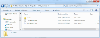
1. As shown in the following figure, create a folder for your project (here is PCL_sample). Within the folder, create one empty folder (for CMake output), a CMake config file (CMakeLists.txt) and entry of your project (pcd_write.cpp). An example of content of "CMakeLists.txt" and "pcd_write.cpp" can be found here.

Before CMake the project
2. Open the CMake and choose the directory for the source code and where to build the binaries, then click Configure.
Choose directory in CMake
3. In the pop-up window, choose the Visual Studio 10 (if your are using 64bit please select the corresponding one) and then click finish.
Pop-up window
4. After the build is finished, click the Generate button and you will see the VS2010 solution files are created in the build folder.
Finish build in CMake
VS 2010 solution file is created by the CMake
  • Result
After compiling and running the program in VS2010, a point cloud data file (test_pcd.pcd in figure) is created. The basic data type is PointCloud which can be saved in *.pcd file by following format:

# .PCD v0.7 - Point Cloud Data file format
VERSION 0.7
FIELDS x y z
SIZE 4 4 4
TYPE F F F
COUNT 1 1 1
WIDTH 5
HEIGHT 1
VIEWPOINT 0 0 0 1 0 0 0
POINTS 5
DATA ascii
1.28125 577.09375 197.9375
828.125 599.03125 491.375
358.6875 917.4375 842.5625
764.5 178.28125 879.53125
727.53125 525.84375 311.28125
Output of pcd_write.cpp


07 February 2013

Statistical Shape Model (SSM)


  • What is shape?

 The shape is usually defined as the geometric information invariant to a particular class of transformation (similarity transform: translation, rotation and scaling)

The statistical models represent shape of an object by a set of points. The points can be parameterized and controlled so that the shape of the object can be changed.
The purpose of Statistical Shape Model (SSM) is to derive models which allow us to 1) analyse new shapes, and 2) synthesise shapes similar to those in a training set.

Note: The shapes don't need to be represented in space, but also in time or intensity. For examples:
3D shapes: composed of points in 3D space/ points in 3D space + time (image sequence)
2D shapes: composed of points in 2 D space/ space + time
1D shapes: points along a line/ intensity values sample in an image


  • Suitable Landmarks
Good landmarks are points which can be consistently located from one image to another. A training set can be generated by a human expert who annotates each of a series images with a set of corresponding points. Since it can be time consuming and tedious, some automatic and semi-automatic method are being developed.
In two dimensions suitable landmarks can be placed at clear corners of object boundaries, 'T' junctions between boundaries or easily located biological landmarks.
Representation: If a shape is described n points in d dimensions we represent the shape by a nd element vector formed by concatenating the elements of the individual point position vectors. For example, in a 2D image the n landmark points, {(xi,yi)}, can be represented as 
(this is an example in the training set)
  • Aligning the Training Set
One of the most popular approach to align two shape is Procrustes Analysis which aligns each shape so that the sum of distances of each shape to the mean is minimised.  
where m is the mean of the shapes and Ti is the similarity transformation.
Here is an iterative approach to align shapes:


  • Modelling Shape Variation
Modelling shape variation
  • Choice of Number of Modes

  • Example of Shape Models


Reference:
1. http://www.cmlab.csie.ntu.edu.tw/~cyy/learning/papers/PCA_ASM.pdf

03 February 2013

Kinect RGB & depth camera calibration

As mentioned in previous post, Kinect has two cameras, one for capturing colour image and the other for depth image. These two images don't match with each other (i.e two pixels at the same location in RGB and depth image do not correspond to the same location in a scene). In order to get the depth information of the colour image (or the colour information for depth image), we need to calibrate the two camera.
The idea of this calibration (and images) is come from here.

Step 1: Capture IR image (not depth) and colour images by using libfreenect (update: the newest Kinect for Windows SDK 1.6 also provide raw IR image). We need to block the IR emitter to get clean image instead of infrared spots for better corner detection in calibration. If the IR image is dark which means not enough IR rays are reflecting from the chessboard pattern, the Halogen lamp (heat) to illuminate the scene.
IR image (IR emitter is blocked) and Colour image captured by the corresponding camera

Step 2: w.r.t each camera, use calibration toolbox (e.g. GML) to get intrinsic parameters, K_ir and K_rgb and distortion parameters.

Step 3: Use toolbox to calculate extrinsic parameters of two cameras and get their relative transformation by using this equation:
where is the transformation from a to b. Since we already known the transformation from world coordinate frame to RGB and IR camera frame (extrinsic parameters), the relative position between IR and RGB camera can be found.

Step 4: Compute depth of RGB image from depth image provided by IR camera.

  • Step 4-1: for each pixel p_ir in IR image, back-project it to 3D world then get 3D point P_ir:
P_ir = inv(K_ir) * p_ir


  • Step 4-2: transform the 3D point from IR coordinate frame to RGB coordinate frame:
P_rgb = R*P_ir + t


  • Step 4-3: project the 3D point to RGB image coordinate:
p_rgb = K_rgb*P_rgb
The depth of the pixel p_rgb is the Z value of P_rgb.

P_ir : 3D point in the IR camera's coordinate system
R, t : Relative transformation between two cameras
P_rgb : 3D point in the RGB camera's coordinate system
p_rgb : The projection of P_rgb onto the RGB image


Base on the same idea, the colour information of the depth image can be calculated in the same way.

Notes:
The depth images provided by the IR camera express the depth information as discretized values in certain range, rather than actual distances. The depth-to-distance is required to convert the raw depth values into real distances. The calibration process is straightforward. The Windows SDK or other libraries also provide actual distance but the precision may not good enough. The depth-to-distance calibration will be done depends on the accuracy of the library during experiment.

02 February 2013

Calibration parameters

Intrinsic parameters describe the property of camera itself and don't depend on the scene viewed, they are:
  • Focal length (fc): measure camera's ability to converge/diverge light.
  • Principle point (cc): where optical axis intersect with image plane.
  • Skew coefficient (alpha_c): defining the angle between the x and y pixel axes.
  • Distortions (kc): normally include radial and tangential distortions for colour camera.
Let P be a point in space of coordinate vector XXc = [Xc;Yc;Zc] in the camera reference frame. Let xn be the normalized (pinhole) image projection:
 

Let r2 = x2 + y2After including lens distortion, the new normalized point coordinate xd is defined as follows:
where dx is the tangential distortion vector:
 
kc(1), kc(2), kc(5) are radial distortion coefficients, kc(3), kc(4) are tangential distortion coefficients. For most colour camera, this distortion model is enough. However, for the depth camera, disparity to depth values may be considered.
Once distortion is applied, the final pixel coordinates x_pixel = [xp;yp] of the projection of P on the image plane is:
Writ the equations in matrix:
where KK is known as the camera intrinsic matrix, and defined as follows: 
It is suggested that we usually ignore the skew factor (alpha_c=0) in practice as currently manufactured camera used rectangular pixels. Furthermore the 6th order distortion model may not be necessary for standard filed of views (non wide-range camera), so the kc(5)=0

Extrinsic parameters denote the transformation from 3D world coordinate to 3D camera coordinate.
For rigid transformation we have:
Rotation matrix (Rc): 3x3
Translation vector (Tc): 3x1

Let P be a point vector XX = [X;Y;Z] in the world reference frame
Let XXc = [Xc;Yc;Zc] be the coordinate vector of P in the camera reference frame.
Then XX and XXc are related to each other through the following rigid motion equation:
XXc = Rc * XX + Tc